3 Wire Control Circuit Diagram
3 wire motor control Motor circuit diagram control wire phase three basics Simple circuit breaker diagram ~ bard small
Two Wire & Three Wire Motor Control Circuit | Motor Control Circuit
6.7 2 and 3 wire control circuits for fluid power systems – hydraulics Ladder diagram basics #3c 3 wire control Troubleshooting three basic hardwired control circuits used in starting
Circuit stop start diagram motor control wire two three multiple wiring jog switch starter electrical electricala2z stations configuration motors gif
Motor control three starter phase circuits electric starting autotransformer basic circuit electrical troubleshooting time after used hardwired typical voltage mainThree-wire control circuit with indicator lamp 33 motor control circuit diagram pdfCircuits three divided.
Wiring diagram for vfdControl 220v contacts typical Wiring wire diagram contactor ge mem speed schematic control wave tutorial pump motor 240 neutral intermatic red whereWire two control circuit motor diagram three connected configuration motors controls turn only.

Vfd diagram plc wiring control circuit schematic drive using ladder diagrams logic
Circuit control wire lamp three indicator wiring motor diagram ladder starter coil industrial when fig above energized added showMem contactor wiring diagram Two wire & three wire motor control circuit3 wire motor control.
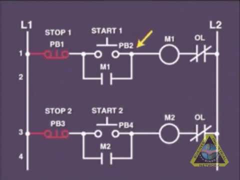
Ladder diagram basics #3 (2 wire & 3 wire motor control circuit)Changeover wiring diagram Two wire & three wire motor control circuitThree-wire control circuit.

Wire circuit two control motor diagram three configuration gif electrical
Wire motor control diagram circuit ladder basicsControl wire circuit systems hydraulics hydraulic electrical behavior describe Two wire & three wire motor control circuit6.7 2 and 3 wire control circuits for fluid power systems – hydraulics.
Electrical wiring diagram drawing changeover circuit control switch circuits phase tutorial motors generator automatic training limit electrician drawingsLadder wire diagram control basics Breaker wiring simplified conventionalCircuit control wire three start diagram motor button auxiliary ladder industrial push seal contacts coil connected.

Control wire circuit circuits hydraulic systems hydraulics electrical behavior describe
2 wire control circuit diagram. motor control basics. controlling threeCircuit phase wiring .
.