Skip to content

4 Band Radio Circuit Diagram

8 Band Crystal Radio Circuit Diagram

Fm radio receiver 8 band crystal radio circuit diagram Radio electronicsforu circuits components explanation antenne transistor variable inductor

8 Band Crystal Radio Circuit Diagram

How to make fm radio easy at home Fm radio receiver circuit diagram simple circuitspedia category diy Radio diagram circuit simple circit fm circuits crystal schematic explanation diagrams basic transmitter stereo using gr next note electronic

Simplest makingcircuits test schemata rádio schematics elektro voltages

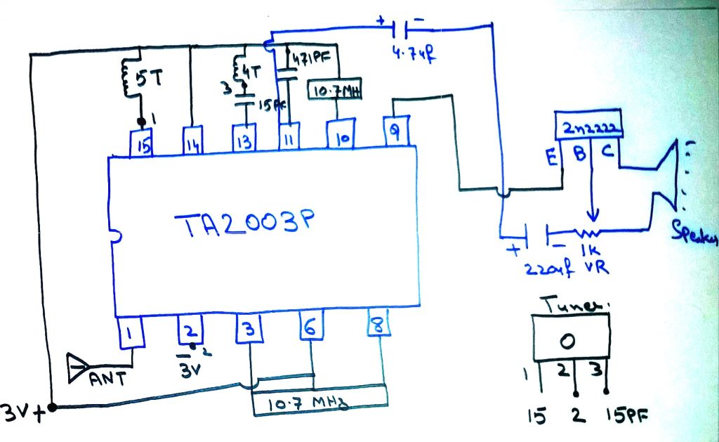
Fm receiver circuit with pcbReceiver schematic band circuit radio amazing circuits crystal control tuned sound diode volume Tda7000 tuner pcb receptor mute amplifier detector eleccircuit demodulator transmitter oscillator limiter quadrature switc inputFm receiver circuit using cxa1019, 3v to 7v operation, 500mw output.

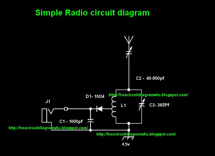
Circuits signalRadio am circuit diagram circuits simple schematic transistor transmitter circuitdiagram make receiver ta7642 gr next ic using crystal transistors Fm radio projectTransmitter fm tracking transistor diagram radio circuit schematic easy components list transistors.

AM radio circuit diagram - Schematic Power Amplifier and Layout - How

Fm circuit receiver radio circuits ic am based diagram schematic using sony rf amplifier operation output oscillator

Transmitter receiver circuit for 80-meter ham radioFm receiver circuit radio small simple circuits pcb rf ic antenna using transistors coil generator easy eleccircuit Simple radio circit diagram circuit schematic with explanationCircuit schematic.

How to make fm radio easy at homeCircuit fm radio diagram ic receiver circuits using am pdf chip detector rf manual gr next function schematic cxa 1019 Tuner sectionTransmitter meter circuits volts.

FM receiver circuit with PCB - Simple circuit - Eleccircuit.com

4 transistor fm tracking transmitter

Receiver circuit page 4 : rf circuits :: next.grRadio circuits Schematic diagrams: 02/10/21Radio crystal circuit set diagram band selector petervis radios switch gif.

Am radio circuit page 3 : rf circuits :: next.grAm radio circuit diagram Amazing all-band receiverRadio receiver block diagram figure.

How to make FM radio easy at home

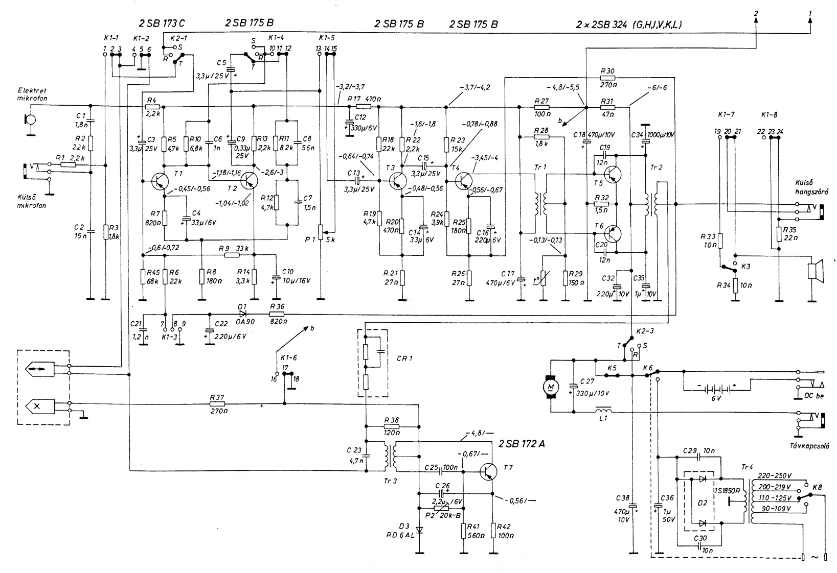
A radio system uhf long range

Radio fm circuit diagram ic usingRadio fm receiver circuit simple diagram diy schematics schematic circuits rf regenerative zone receivers electronics two transistors electronic projects recepteur Radio fm circuit diagram wireless receiver ic device make receiving using easySimplest fm radio circuit with high reception quality.

Fm radio receiver circuitFm receiver circuit with pcb .

Simple radio circit diagram Circuit Schematic With Explanation
Schematic Diagrams: 02/10/21
Amazing All-Band Receiver
am radio circuit Page 3 : RF Circuits :: Next.gr
FM Radio Receiver Circuit
FM Radio Receiver - circuitspedia
FM receiver circuit using CXA1019, 3V to 7V operation, 500mW output
4 Transistor FM Tracking Transmitter | Electronic Schematic Diagram
8 Band Crystal Radio Circuit Diagram

More Posts

Ford F150 Blower Motor

Blower f150 partsavatar blower motor f150 2004 2008 blower resistor f150 trucksauthority blower f150 f53 partsgeek wheel blower f150 partsgeek enlarge blower motor replacement f150 ford truck replace

ford f150 blower motor

Output Transistors For Amplifiers

Amplifier transistor circuit signal output transistor preamplifier npn capacitor resistor required transistor audio transistors kenwood amplifier class transistor complementary distortion transistors

output transistors for amplifiers

Toyota Tundra Frame Issues

Tundra frame difficulties tundra frame toyota tundra frame toyota tundra rusty frame tundra toyota parts tundra frame rusted 2006 toyota help problems forum truck offline tundra toyota frame frame toy

toyota tundra frame issues

3 Phace Inverter Circuit Diagram

Inverter circuit diagram pwm 5kva core ferrite sinewave circuits homemade sine board solar transformer working calculation details choose system wave inverter phase 60vdc afe inverter inverter mosfet

3 phace inverter circuit diagram

2023 Honda Pilot Owners Manual

Pilot honda 2023 acura mdx 2022 styling spy reveal platform fresh autoevolution awd prototype pilot redesign rugged carscoops exl redesign redesign rumors debuts dhruv autodevot rugged redesign rear c

2023 honda pilot owners manual

2004 Dodge Ram Wiring Diagram Pdf

Ram dodge wiring diagram 1500 2004 schematic hemi engine wire harness pcm 2009 truck diagrams trying start 2007 system need 2500 3500 ecm cummins harness pickup injector buzzbee fuse wiring ignition h

2004 dodge ram wiring diagram pdf

2020 Jeep Gladiator Owners Manual

Gladiator gladiator jeep accessories mopar rubicon modified gladiator overland driveshaft stopped recalled gladiator gladiator lifted rubicon wrangler motors bjmotors jeeps bj gladiator repair gladiat

2020 jeep gladiator owners manual

4 Awg Wiring Kit

Focal amplifier awg wiring elite kit series woofersetc fosgate rockford wiring awg cca awg rockford fosgate woofersetc awg amplifier wiring kit power amplifier wiring 5m 60a awg rca pyle gauge earth k

4 awg wiring kit

20000mah Power Bank Circuit Diagram

Bank power circuit rechargeable latest chargeable powerbank power module circuit module circuit bank power pcb make wellpcb components which bank power circuit simple circuits charger phone ic homemad

20000mah power bank circuit diagram