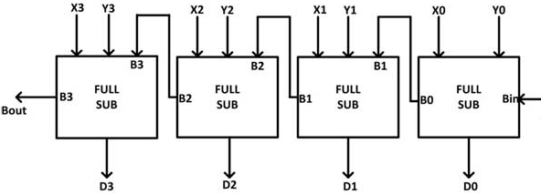
4 Bit Subtractor Circuit Diagram
Let's learn computing: 4 bit adder/subtractor circuit Bit adder subtractor circuit carry ripple logic Subtractor adder
Full Subtractor Circuit and Its Construction
4 bit subtractor circuit Subtractor circuitdigest Parallel subtractor
Solved consider the 4-bit adder/subtractor circuit displayed
Adder serial bit subtractor parallel load number xilinx two negated ise schematics drawnSolved adder and subtractor 4 bit circuit i have the next Digital logic4-bit serial adder/subtractor with parallel load – altynbek isabekov.
Subtractor parallel bit workingSubtractor adder bit circuit using logisim pint schematic 4-bit binary adder-subtractorFull subtractor circuit and its construction.

Subtractor bit implementation comparator using mux 2bit helps hope information these stack same
Circuit adder bit subtractor using subtraction logic carry sub digital borrow control input additional signal add sponsored links note lowAdder subtractor bit circuit add sub questions overflow complement logic detection carry addition designing control zero line digital find Adder bit subtractor circuit values following consider input mode has help steps solve thank solved questionsMake adder subtractor bit carry ripple verilog binary using 4bit want subtraction addition operation output hdl which has value.
4 bit full adder/subtractor circuit .