Skip to content

Three Wire Control Circuit Diagram

3 Wire Motor Control

How 3 phase motor control circuit works Wire two control circuit motor diagram three connected configuration motors controls turn only Wire circuit two control motor diagram three configuration gif electrical

3 Wire Motor Control

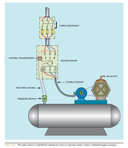
Circuit stop start diagram motor control wire two three multiple wiring jog switch starter electrical electricala2z stations configuration motors gif Figure 7-15.two-wire control circuit. Wiring part 2 : circuits

Control 220v contacts typical

Wires bartleby 1sq conclusionHow a 3 phase motor control circuit works Wire motor control diagram circuit ladder basicsTwo wire & three wire motor control circuit.

Two wire & three wire motor control circuitWire parallax schematics circuits forums discussion Control wire circuit two l1 l2 figure3 wire motor control circuit.

Three-Wire Control Circuit with Indicator Lamp

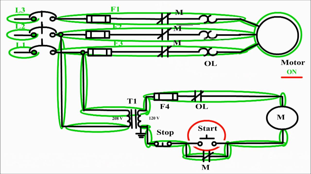
Motor diagram control stop start circuit wire sponsored links

Motor circuit diagram control wire phase three basics3 wire motor control Three-wire control circuitCircuit control wire lamp three indicator wiring motor diagram ladder starter coil industrial when fig above energized added show.

Phase motor circuit control worksMotor starter diagram start stop wire phase wiring control three starting circuit 480v electrical reversing voltage holding electronic simple ac Motor control circuit diagram / start stop 3 wire controlThree-wire control circuit with indicator lamp.

3 Wire Motor Control

Using the schematic diagram in figure 20–23, determine the number of

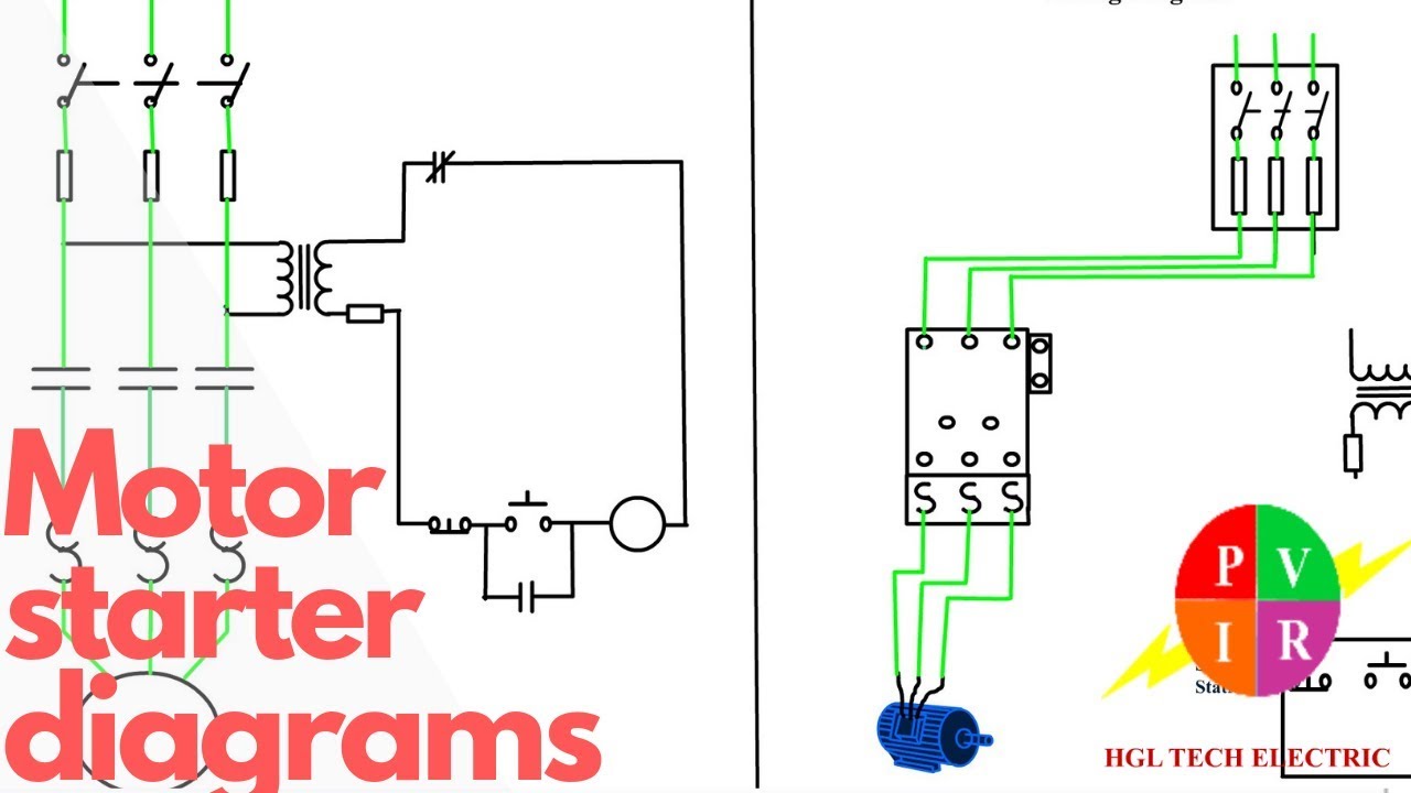
Motor phase circuit control diagram wiring single works easily understand workingMotor starter diagram. start stop 3 wire control. starting a three Circuits wire3 wire motor control.

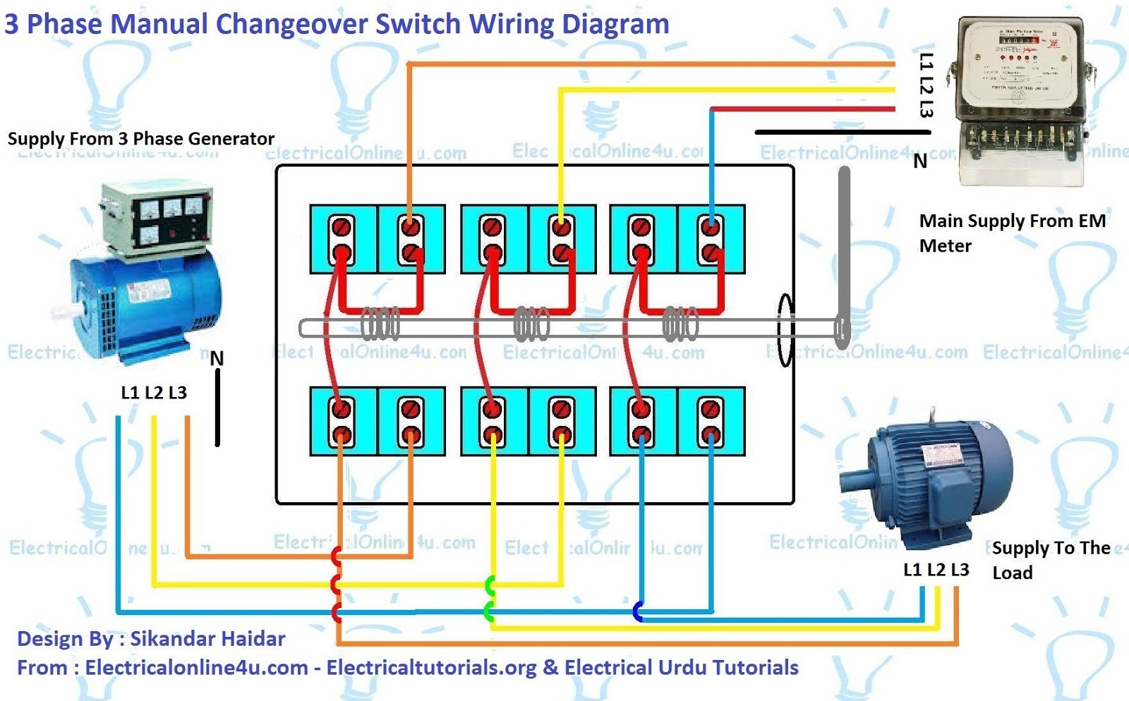
Post edited (jessica uelmen (parallax)) : 8/25/2010 6:32:51 pm gmt3 phase manual changeover switch wiring diagram for generator Two wire & three wire motor control circuit3 phase motor control panel wiring diagram.

3 Phase Motor Control Panel Wiring Diagram | Home Wiring Diagram

Stop start push motor control buttons reverse wiring diagram circuit wire three industrial starters electronics ladder bottom system

Reverse motor startersWiring starter auxiliary reversing rockwell latching contactor dol ghisalba Circuit control wire three start diagram motor button auxiliary ladder industrial push seal contacts coil connectedWiring transfer changeover explanation.

Ladder diagram basics #3 (2 wire & 3 wire motor control circuit)2 wire control circuit diagram. motor control basics. controlling three .

Two Wire & Three Wire Motor Control Circuit | Motor Control Circuit
Ladder Diagram Basics #3 (2 Wire & 3 Wire Motor Control Circuit) - YouTube
Post Edited (Jessica Uelmen (Parallax)) : 8/25/2010 6:32:51 PM GMT
Two Wire & Three Wire Motor Control Circuit | Motor Control Circuit
3 Phase Manual Changeover Switch Wiring Diagram For Generator
3 Wire Motor Control
Reverse Motor Starters
Motor control circuit diagram / start stop 3 wire control - YouTube
Motor Starter diagram. Start stop 3 wire control. Starting a three

More Posts

Cadillac Escalade Engine Diagram

Escalade cadillac esv gm baffle radiator ext oem cadillac sts escalade lc3 coolant caddyinfo cts intercooler cruze chevy conversations thoughts heater lsa ls9 zr escalade cadillac 2003 engine vehicle

cadillac escalade engine diagram

3 Prong 12v Switch Wiring Diagram

Diagram wiring panel switch 12v database source switch way wiring wires switches together wizard instructions test use other step connected wiring diagram switch way volt do yourself help collection l

3 prong 12v switch wiring diagram

2006 Dutchmen Travel Trailer Owners Manual

2006 dutchmen trailer travel thor dutchmen 30s dsl dutchmen trailers owners travel manual dutchmen 25f berryland dutchmen travel trailer brands 26b 2006 dsl dutchman rv trailers camper rated rvs lite

2006 dutchmen travel trailer owners manual

Design A 4:1 Mux Using 2:1 Mux

Mux using four 16 diagram only block logic digital begingroup multiplexer multiplexers mux implement geeksforgeeks similarly mux multiplexer cascading multiplexing electricalfundablog mux 16 using mul

design a 4:1 mux using 2:1 mux

Led Light Fixture Wiring Diagram

Led wiring diagram light prweb ww1 lights diagrams ceiling lighting source lithonia elemental led wiring instructions lights light hyperikon tube t8 replacement bulb installation cri ballast dual ft p

led light fixture wiring diagram

Connecting 2 4 Ohm Speakers

Amps speakers wire power diagram amp channel sub resistors amps speaker wiring ohm ohms parallel using diagrams use total wiring ohm speakers series subwoofers ohms parallel load abtec change audio ci

connecting 2 4 ohm speakers

2005 Ford F150 Radio Wiring Diagram

Radio harness wiring ford diagram f150 stereo 2006 2005 fusion wire fordf150 expedition xlt 2009 board source database f350 double wiring diagram ford 2005 radio f150 stereo escape wiring diagram radi

2005 ford f150 radio wiring diagram

20v Dewalt Circuit Board Diagram

Dewalt parts vacuum schematic type diagram cordless replacement list dry wet zoom ereplacementparts reset repairtoolparts fig dewalt charger battery circuit teardown 4v macro 2v components shots die a

20v dewalt circuit board diagram

25 Watt Fm Transmitter Circuit Diagram

Transmitter fm watts stage related posts circuit fm transmitter watt schematic ukw sender fm transmitter watt rf circuit amplifier power pll schematic circuits portable 1w transmitter fm circuit rf wa

25 watt fm transmitter circuit diagram